How To Wire A Servo Motor
Jan 18, 2024
Wiring a servo motor involves connecting it to a power source and a control signal in a specific way to enable precise control of its movement. Servo motors are widely used in various applications, such as robotics, automation, and model aircraft, due to their ability to provide accurate and controlled angular movement. In this guide, we will explore the step-by-step process of wiring a servo motor, covering the essential components and connections.
Understanding the Basics
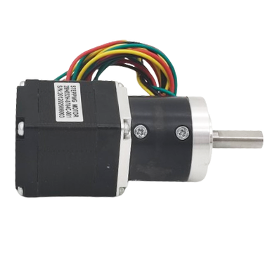
Before delving into the wiring process, it's crucial to understand the basic components of a servo motor and how it operates. A servo motor typically consists of three wires:
Power (V+): This wire delivers the necessary electrical power to operate the motor. The voltage specifications can fluctuate based on the servo model, typically falling within the standard range of 4.8 to 6 volts for most servos.
Ground (GND): This cable is connected to the ground or common reference point of the power supply. It completes the electrical circuit and ensures proper functioning of the servo motor.
Control (Signal): The control wire carries the signal from a microcontroller or servo controller to the servo motor, instructing it on the desired position. This signal is usually a PWM (Pulse Width Modulation) signal.
Step-by-Step Wiring Guide
1. Identify the Wires:
Before starting the wiring process, identify the three wires of your servo motor: Power (V+), Ground (GND), and Control (Signal). Additionally, you need a stable power source within the specified voltage range.
2. Power Connection:
Connect the Power (V+) wire of the servo to the positive terminal of your power source. This is typically the red wire on the servo. Likewise, connect the Ground (GND) wire (usually brown) to the negative terminal or ground of the power source.
3. Voltage Regulation (if needed):
Depending on your application, you might need to regulate the voltage supplied to the servo motor. This ensures that the voltage remains within the specified range to prevent damage to the servo. A voltage regulator can be added between the power source and the servo motor.
4. Signal Connection:
Connect the Control (Signal) wire (commonly yellow or orange) to the PWM output of your microcontroller or servo controller. Ensure that the signal wire is connected to the correct pin on your controller.
5. Wiring Integrity Check:
Double-check all connections to ensure they are secure and correctly aligned. Any loose connections can lead to erratic behavior or malfunction of the servo motor.
6. Programming and Testing:
Write a program or use a servo tester to generate PWM signals that command the servo to move to specific positions. Test the servo's response to ensure it moves smoothly and accurately according to the control signals.
7. Mechanical Linkage:
If your application involves moving a mechanical component, such as an arm or a wheel, ensure that the servo is mechanically linked to the part it needs to control. This linkage can involve using gears, levers, or other mechanical components.
8. Fine-Tuning:
Fine-tune your control signals to achieve the desired precision and range of motion. This may involve adjusting the pulse width or programming parameters in your control software.
9. Power Supply Considerations:
Ensure a stable and reliable power supply for your servo motor. Battery packs, voltage regulators, or external power sources may be necessary depending on the specific requirements of your application.
Wiring a servo motor involves a systematic process that includes understanding the basic components, identifying wires, making precise connections, and thorough testing. Following these steps will ensure that the servo motor operates smoothly and accurately in diverse applications.